Misread by Design: How GD&T Misinterpretation Is Silently Eroding Profit Margins Across American Manufacturing
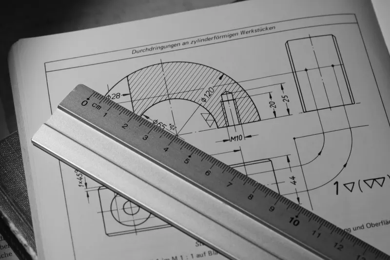
There is a language spoken on every engineering drawing produced in the United States, and a significant portion of the people responsible for acting on those drawings do not fully understand it. Geometric dimensioning and tolerancing — GD&T — is the standardized symbolic system that communicates not just the size of a feature, but its form, orientation, location, and relationship to other features. It is, in theory, a precision instrument for transferring design intent from the engineer's mind to the machinist's hands. In practice, it is frequently misread, inconsistently applied, and quietly responsible for millions of dollars in annual rework across American industry.
The problem is not that GD&T is inherently flawed. Governed by ASME Y14.5 and widely adopted across aerospace, automotive, defense, and general industrial manufacturing, it is among the most rigorously developed technical standards in existence. The problem is the gap between the standard's sophistication and the average organization's command of it — a gap that widens every time a drawing moves between departments, suppliers, or generations of engineers.
Where the Breakdown Actually Begins
Most GD&T failures do not originate on the shop floor. They begin much earlier, at the design stage, where engineers apply geometric controls with incomplete training or without a clear understanding of how those controls will be measured and verified downstream. A position tolerance applied to a bolt-hole pattern, for example, carries specific implications for datum selection, measurement setup, and acceptable gauge methodology. When those implications are not fully understood by the engineer specifying the control, the tolerance becomes functionally ambiguous — even if it appears precise on paper.
The ambiguity compounds as the drawing travels outward. A quality engineer interprets a profile tolerance differently than the machinist who set up the part. A supplier's CMM operator applies a datum reference frame that differs from what the design engineer intended. An inspector at final receiving rejects a component that would have passed had the measurement been performed in accordance with the drawing's true intent. Each of these scenarios represents a failure of translation, not a failure of capability.
In facilities where GD&T training is inconsistent or outdated — and that describes a substantial share of US manufacturing operations — these translation failures accumulate. They show up as elevated scrap rates, supplier disputes, repeated first-article failures, and production delays that no one can fully explain because no one has traced the root cause back to the drawing.
The Real Cost of Getting It Wrong
Quantifying the financial impact of GD&T misinterpretation is difficult precisely because the costs tend to be distributed and disguised. Rework is logged as a quality expense. Supplier rejections appear as procurement friction. Production delays are absorbed into schedule buffers. No single line item says "GD&T error," which means the problem rarely receives the focused attention it deserves.
Consider a common scenario in precision component manufacturing: a critical mating assembly fails functional testing during final integration. The investigation reveals that a cylindricity control on a bore was interpreted by the machining supplier as a simple diameter tolerance, resulting in a part that measured within dimensional limits but exhibited enough form variation to cause interference under load. The rework cost — including disassembly, re-machining, re-inspection, and schedule recovery — runs into tens of thousands of dollars. The drawing was technically correct. The interpretation was not.
Multiply scenarios like this across a facility processing hundreds of part numbers, and the cumulative financial exposure becomes significant. Industry estimates suggest that inspection and rework costs tied to drawing interpretation errors can account for between five and fifteen percent of total quality-related expenditure in complex manufacturing environments — a figure that represents a substantial and largely preventable drain.
The Communication Fracture Between Design and Production
At the heart of most GD&T failures is a structural communication problem. Design engineering and manufacturing operations frequently operate with different vocabularies, different priorities, and different levels of exposure to the ASME Y14.5 standard. In many organizations, design engineers receive formal GD&T instruction as part of their education or early career development, while machinists, programmers, and quality technicians acquire their understanding informally — through experience, tribal knowledge, and whatever interpretation happened to be in use when they started the job.
This creates an environment where the same symbol on a drawing can mean different things to different people in the same building. A runout callout, a true position control, a composite tolerance frame — each carries specific measurement and functional implications that are not self-evident to someone who has not studied the standard in depth. When those implications are misunderstood, the part produced may satisfy the individual's interpretation of the drawing without ever satisfying the engineer's actual intent.
The fracture is often invisible until something goes wrong. And by the time it surfaces — in a rejected lot, a failed assembly, a customer complaint — the cost of correction has already been incurred.
A Framework for Getting GD&T Right
Addressing GD&T misinterpretation requires more than a training seminar. It demands a systematic approach that touches drawing creation, internal review, supplier communication, and measurement practice simultaneously.
Standardize datum selection and application. Many interpretation failures stem from ambiguous or poorly chosen datum reference frames. Establishing internal standards for datum selection — tied explicitly to functional requirements and measurement accessibility — reduces the interpretive latitude that leads to inconsistency.
Require cross-functional drawing review. Before a drawing is released, it should be reviewed not only by engineering but by the manufacturing engineers, quality personnel, and, where applicable, key suppliers who will be responsible for producing and inspecting the part. This practice surfaces interpretation conflicts before they become production problems.
Invest in structured, role-specific GD&T training. Generic GD&T courses serve as a foundation, but the most effective training is tailored to the specific roles and responsibilities of the people receiving it. A CMM operator needs depth in measurement setup and datum simulation. A machinist needs clarity on how geometric controls translate to fixturing and process control. A design engineer needs command of functional tolerance analysis. Each role requires a different emphasis.
Align measurement methods to drawing intent. The method used to verify a geometric control must reflect the functional intent behind it. If a position tolerance is specified to ensure assembly interchangeability, the measurement approach should simulate the assembly condition — not simply record a coordinate measurement that satisfies the number without validating the function.
Treat supplier GD&T alignment as a procurement requirement. For organizations that rely on external suppliers for precision components, GD&T alignment should be part of the supplier qualification process. Confirming that a supplier's quality team interprets key controls consistently with design intent — before the first production run — is far less expensive than resolving the dispute after delivery.
The Competitive Case for Precision Communication
US manufacturers operating in high-precision segments — aerospace, defense, medical, advanced industrial — compete on their ability to produce complex components to exacting specifications, reliably and repeatedly. GD&T, properly applied, is one of the foundational tools that makes that capability possible. It allows tighter tolerances to be specified with greater confidence, enables more efficient inspection processes, and provides a common technical language that supports collaboration across the supply chain.
When that language is misread, the competitive advantages it enables are replaced by costs that compound quietly and erode margins without ever appearing on a single line of the income statement. Closing the interpretation gap is not a theoretical exercise in standards compliance. It is a direct investment in first-pass quality, supplier reliability, and the kind of operational precision that separates manufacturers who compete on capability from those who compete on price alone.
The geometry is on the drawing. The question is whether everyone reading it is speaking the same language.